VIBRATING CORD FOR GEOTECHNICS
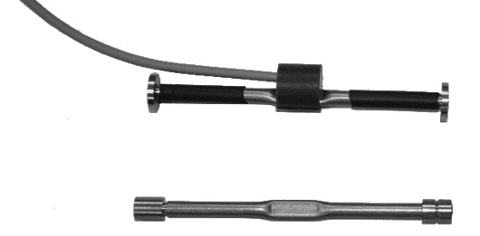
The BA-EST / CV vibrating string extensometer bars are used to measure the existing tension states in load-bearing structures or to monitor
the tensions existing in the ribs during tunnel excavation. This control is necessary for checking the tensions and deformations of both
temporary and permanent support structures.
The vibrating string strain bars consist of a stainless steel tube inside which a thin rope, fixed at both ends, is vibrated by an excitation coil. An
internal thermistor also measures the temperature. The BA-EST / CV strain gauge rod can work either tensile or compressive, and the
sensitized part is resin-coated in order to preserve the functionality of the instrument in case of impact or immersion.
Data can be read out by using the portable control unit or by an automatic data acquisition system, designed to carry out continuous
monitoring. The bar is watertight, can be applied externally to stressed structures or drowned in concrete castings for stress measurements
![]() Click to enlarge image
Click to enlarge image

| Material | Stainless steel |
| Measuring range | 3000 μ ɛ |
| Sensitivity | 1 μ ɛ |
| Operating temperature | -20 / +80°C (-4 / +176°F) |
| Protection class | IP 68 |
| Sensor type | vibrating string |
| Total accuracy | < 0.5% of full scale |
| Internal thermistor | NTC 3 kΩ |
| Cord length | 153 mm (welding), 145 mm (concrete) |
| Type of installation | Welding on metal, sinking in concrete |
| Typical frequency | 800 Hz |
| Resistance of the spool | 150 Ω |
| Dimensions welding bar | 165 x 25 x 25 mm (6.49 x 0.98 x 0.98 in.) |
| Dimension concrete bar | 157 x 25 x 25 mm (6.18 x 0.98 x 0.98 in) |
| Standard cable length | 3 m – 4 x 0,25 (shield not connected to the load cell body) |
General precautions to be followed in the installation and assembly of load cells: